
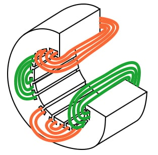
Single Coil of a Single Phase Motor
The single coil of a single-phase induction motor does not produce a rotating magnetic field, but a pulsating field reaching maximum intensity at 0° and 180° electrical.

Another view is that the single-coil excited by a single-phase current produces two counter-rotating magnetic field phasors, coinciding twice per revolution at 0° (Figure above-a) and 180° (figure e). When the phasors rotate to 90° and -90° they cancel in figure c. At 45° and -45° (figure b) they are partially additive along the +x axis and cancel along the y-axis. An analogous situation exists in figure d. The sum of these two phasors is a phasor stationary in space, but alternating polarity in time. Thus, no starting torque is developed.
However, if the rotor is rotated forward at a bit less than the synchronous speed, It will develop maximum torque at 10% slip with respect to the forward rotating phasor. Less torque will be developed above or below 10% slip. The rotor will see 200% - 10% slip with respect to the counter-rotating magnetic field phasor. Little torque (see torque vs slip curve) other than a double frequency ripple is developed from the counter-rotating phasor. Thus, the single-phase coil will develop torque, once the rotor is started. If the rotor is started in the reverse direction, it will develop a similar large torque as it nears the speed of the backward rotating phasor.
Single-phase induction motors have a copper or aluminum squirrel cage embedded in a cylinder of steel laminations, typical of polyphase induction motors.
Permanent-Split Capacitor Motor
One way to solve the single phase problem is to build a 2-phase motor, deriving 2-phase power from single phase. This requires a motor with two windings spaced apart 90° electrical, fed with two phases of current displaced 90° in time. This is called a permanent-split capacitor motor.

This type of motor suffers increased current magnitude and backward time shift as the motor comes up to speed, with torque pulsations at full speed. The solution is to keep the capacitor (impedance) small to minimize losses. The losses are less than for a shaded pole motor. This motor configuration works well up to 1/4 horsepower (200 watts), though, usually applied to smaller motors. The direction of the motor is easily reversed by switching the capacitor in series with the other winding. This type of motor can be adapted for use as a servo motor, described elsewhere in this chapter.
Single-phase induction motors may have coils embedded into the stator for larger size motors. Though, the smaller sizes use less complex to build concentrated windings with salient poles.
Capacitor-Start Induction Motor
In the figure below a larger capacitor may be used to start a single-phase induction motor via the auxiliary winding if it is switched out by a centrifugal switch once the motor is up to speed. Moreover, the auxiliary winding may be many more turns of heavier wire than used in a resistance split-phase motor to mitigate excessive temperature rise. The result is that more starting torque is available for heavy loads like air conditioning compressors. This motor configuration works so well that it is available in multi-horsepower (multi-kilowatt) sizes.

Capacitor-Run Motor Induction Motor
A variation of the capacitor-start motor (figure below) is to start the motor with a relatively large capacitor for high starting torque, but leave a smaller value capacitor in place after starting to improve running characteristics while not drawing excessive current. The additional complexity of the capacitor-run motor is justified for larger size motors.

A motor starting capacitor may be a double-anode non-polar electrolytic capacitor which could be two + to + (or - to -) series-connected polarized electrolytic capacitors. Such AC rated electrolytic capacitors have such high losses that they can only be used for intermittent duty (1 second on, 60 seconds off) like motor starting. A capacitor for motor running must not be of electrolytic construction, but a lower loss polymer type.
Resistance Split-Phase Motor Induction Motor
 The two windings are wound with a geometric offset, effectively making a second set of poles phase shifted within the stator. The winding W1 has resistance to provide a phase shift to the current flowing in W1 and we therefore have a "two phase" motor while the switch is closed. The motor can be reversed by reversing the connections of either W1 or W2 (but not both!) The start winding (W1) provides for a rotating magnetic field in one direction enabling the motor to start. |


0 Comments